
|
|
|
Relay Ladder Logic
Expert
|
|
There were automated
manufacturing machines long before there were digital computers, or
even transistors. These machines had their "programming"
embedded in hardware. One of the techniques for building control
logic into a machine using hardware is called relay logic. A relay
is just an electrical switch that is opened and closed using
magnetic energy rather than mechanical energy. A relay has two
states: closed and open. When the relay is closed electrical current can flow
and when it is open current cannot flow. Thus a relay can be thought
of as a single digital element that is either on or off (1 or 0).
Machine designers in the time before computers could wire relays
together to create digital logic.
Relay ladder logic is a software
incarnation of the relay logic that came before it. Machine
programmers create graphical software diagrams that represent these logical
statements. Ladder logic is called ladder logic because the diagrams
resemble ladders with vertical rails on the left and right, and
horizontal rungs running sequentially between the rails.
Hypothetical electrical current flows through the rungs from the
left rail to the right rail.
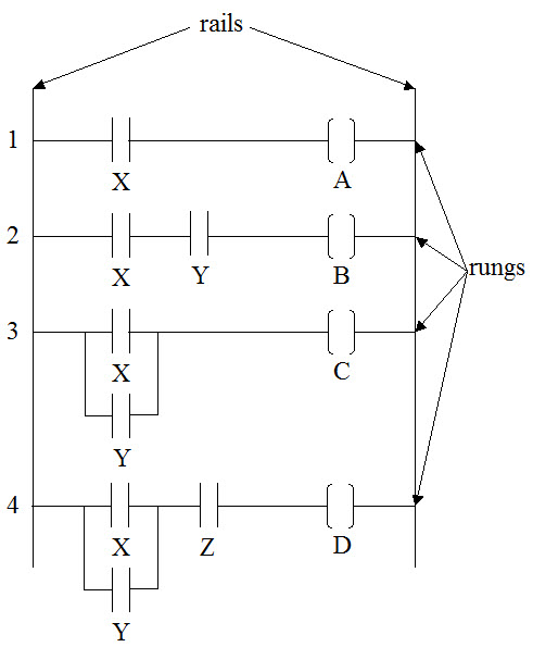
In keeping with the relay
analogy, ladder logic has two main elements: the contact and the
coil. The contact is typically represented by two vertical, straight
lines and the coil is represented by two vertical lines that curve
inward towards each other. When a contact is closed, the
hypothetical current can flow through it and energize the coil. In
the ladder logic diagram below; X, Y and Z are contacts and A, B, C
and D are coils.
We can now analyze the logical statements in
the relay ladder logic diagram below. There are two elements in the
first rung: X and Y. If the contact X is closed, then the
hypothetical current can pass through it and energize the coil A.
The logic statement is, "if X, then A." The second rung
has three elements: X, Y and B. If the contacts X and Y are both
closed, then the hypothetical current can pass through them and
energize the contact B. If either X or Y are open, then the current
cannot flow to energize B. The logical statement for this is,
"if X and Y, then B." The third rung also has three
elements, but they are arranged differently. In this arrangement, if
either X or Y are closed, then the hypothetical current can flow
through to energize C. The logical statement for this rung is
"if X or Y, then C." The fourth rung creates the logical
statement, "if (X or Y) and Z, then D."
|
|
|
I have professional experience
writing relay ladder logic software and expert witness experience analyzing ladder logic software for
Rockwell (aka Allen Bradley), Omron, Siemens and Wago PLCs. I can support your litigation efforts as a relay
ladder logic expert witness. My qualifications include numerous
peer-reviewed
publications and over thirty years of engineering experience
with software, robotics, instrumentation, medical devices,
computer-controlled machines and factory automation.
|
|
|
|
Software,
Robotics and Computer Controlled Machines |
|
|
|
|